|
Architecture of the GSM Network |
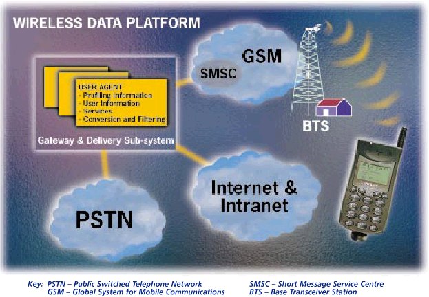
A GSM network is composed of several functional entities, whose functions and interfaces are specified. Figure 1 shows the layout of a generic GSM network. The GSM network can be divided into three broad parts. The Mobile Station is carried by the subscriber. The Base Station Subsystem controls the radio link with the Mobile Station. The Network Subsystem, the main part of which is the Mobile services Switching Center (MSC), performs the switching of calls between the mobile users, and between mobile and fixed network users. The MSC also handles the mobility management operations. Not shown is the Operations and Maintenance Center, which oversees the proper operation and setup of the network. The Mobile Station and the Base Station Subsystem communicate across the Um interface, also known as the air interface or radio link. The Base Station Subsystem communicates with the Mobile services Switching Center across the A interface.
The mobile equipment is uniquely identified by the International Mobile Equipment Identity (IMEI). The SIM card contains the International Mobile Subscriber Identity (IMSI) used to identify the subscriber to the system, a secret key for authentication, and other information. The IMEI and the IMSI are independent, thereby allowing personal mobility. The SIM card may be protected against unauthorized use by a password or personal identity number.
The Base Transceiver Station houses the radio tranceivers that define a cell and handles the radio-link protocols with the Mobile Station. In a large urban area, there will potentially be a large number of BTSs deployed, thus the requirements for a BTS are ruggedness, reliability, portability, and minimum cost.
The Base Station Controller manages the radio resources for one or more BTSs. It handles radio-channel setup, frequency hopping, and handovers, as described below. The BSC is the connection between the mobile station and the Mobile service Switching Center (MSC).
The Home Location Register (HLR) and Visitor Location Register (VLR), together with the MSC, provide the call-routing and roaming capabilities of GSM. The HLR contains all the administrative information of each subscriber registered in the corresponding GSM network, along with the current location of the mobile. The location of the mobile is typically in the form of the signalling address of the VLR associated with the mobile station. The actual routing procedure will be described later. There is logically one HLR per GSM network, although it may be implemented as a distributed database.
The Visitor Location Register (VLR) contains selected administrative information from the HLR, necessary for call control and provision of the subscribed services, for each mobile currently located in the geographical area controlled by the VLR. Although each functional entity can be implemented as an independent unit, all manufacturers of switching equipment to date implement the VLR together with the MSC, so that the geographical area controlled by the MSC corresponds to that controlled by the VLR, thus simplifying the signalling required. Note that the MSC contains no information about particular mobile stations --- this information is stored in the location registers.
The other two registers are used for authentication and security purposes. The Equipment Identity Register (EIR) is a database that contains a list of all valid mobile equipment on the network, where each mobile station is identified by its International Mobile Equipment Identity (IMEI). An IMEI is marked as invalid if it has been reported stolen or is not type approved. The Authentication Center (AuC) is a protected database that stores a copy of the secret key stored in each subscriber's SIM card, which is used for authentication and encryption over the radio channel.
| Send comments to webmaster Copyright © 1997 Derek Mc Donnell. All Rights Reserved. Last updated 07-Apr-1998. |
 |